Pool Control Unit
Motivation
Any extended period away from pool almost always result in pool turning green. Can remotely run the pump with common power control circuits, but without feedback of pH/Chlorine no way to tell what state the pool is in. And the pump settings/control has no remote features.
Goals
- Measure temperature, water volume, salt, chlorine, pH
- Controllable on/off of primary pump and chlorinator strength settings
- Power and flow rates monitoring
- All control / sensing feedback to smart home
- Control acid / chlorine dosing for managing levels automatically
- Future proofing for solar / heating loop
System Design
Basic plumbing loop with indicated sensor locations providing a non-interruptive parallel line for all sensing and dosing requirements. Sense/dose loop can therefore be isolated without effecting the existing pump/filtering loop. One PCB to add active control and feedback to the existing pump/chlorinator controller, and a second PCB for all sensors, communication and usb connection to other PCB.
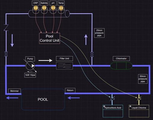
Plumbing layout and sensor locations.
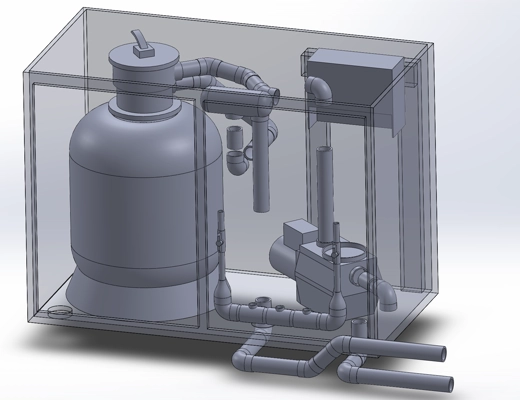
Physical hardware layout concept.
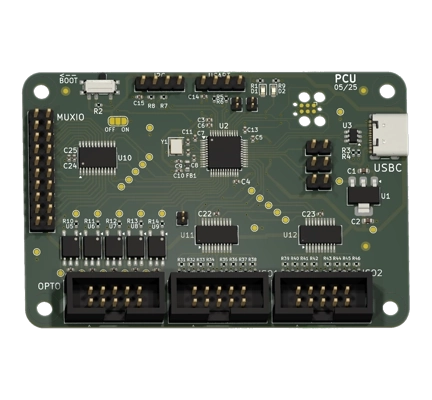
PCB for hacking existing chlorinator and pump controller. Provides USB access with all sensing and control overrides.
Electrical
Inside the Pump controller
- LEDS sensing - 14 total - 2 for errors, 3 for mode, 8 for chlorine strength, 1 for backwash.
- Switches - 4 total - 1 for mode, 2 for chlorine strength, 1 for backwash.
- STM custom PCB. 20+ io total. Comms to second unit.
- Temp sensor?
Existing PCB notes for interfacing https://datasheet4u.com/pdf-down/9/A/1/9A103J_CinetechIndustrial.pdf 2 x 9A103J res networks for switches - 9 pins, 10x10^3 10kOhms, +-5%, A=common 5V 2 x 9A102J res net for leds - 9 pins, 10x10^2 1kOhms, +-5%, A=common 5V
https://www.ti.com/general/docs/suppproductinfo.tsp?distId=10&gotoUrl=https%3A%2F%2Fwww.ti.com%2Flit%2Fgpn%2Fsn74hc165 2 x SN74HC165N for sw Switches are all hooked into 8-bit parellel in series serial out setup. 5V high by default, switches pull to ground. To replicate this, need to pull that line to ground.
https://www.st.com/resource/en/datasheet/hcf4094.pdf 2 x HCF4094BE for leds
Inside the Pump house
Pressure through wall sensor - $28.00 - https://wiki.dfrobot.com/Gravity__Water_Pressure_Sensor_SKU__SEN0257
- Vcc 5V | Vout 0.5->4.5V
Electrical conductivity - $359.95 - https://wiki.dfrobot.com/SKU_SEN0451_Gravity_Analog_Electrical_Conductivity_Sensor_PRO_K_1
- Vcc 3V3-5V | Vout 0->3V
ORP sensor - $244.95 - https://wiki.dfrobot.com/Gravity_Analog_ORP_Sensor_PRO_SKU_SEN0464
- Vcc 5V | Sig -2V->+2V | Vout 0.5->4.5V
pH sensor - $114.95 - https://wiki.dfrobot.com/Gravity__Analog_pH_Sensor_Meter_Kit_V2_SKU_SEN0161-V2
- Vcc 3V3-5V | Vout 0->3V
Hayward Single Speed 2 eco 1HP pump - SIIE 320 - 16m head max.
ENCLOSURE - https://au.rs-online.com/web/p/general-purpose-enclosures/2805424
- Waterproof pass throughs - 4 x sensors (ORP, pH, EC/Temp, )
Firebeetle ESP32 V1
AC/DC unit - 5V & 12V out - https://www.digikey.com.au/en/products/detail/traco-power/TPP-65-221/9382125
2 x Pressure sensor Vcc: 5V, Sig: 0.5V->4.5V
Conductivity Vcc: 3V3-5V, Sig: 0V->3V
ORP Vcc 5V, Sig: 0.5V->4.5V
pH Vcc 3V3, Sig: 0->3V
Current sensing?
Dosing pump controller?
Plumbing Supplies
Check PCU.drawio for loop setup
Main loop plumbing - Holman DN50 pressure pipe AS/NZ rated
Offtake coupling - Pressure Faucet Tee - 50mm -> 1inch - https://www.bunnings.com.au/holman-50mm-x-1-pvc-pressure-faucet-tee_p0285468
REMOVED - Check-valve for right before joining loop - 1MPa max - https://www.bunnings.com.au/holman-50mm-in-line-check-valve_p4790036
Ball valve for offtake and join - https://www.bunnings.com.au/holman-25mm-pvc-ball-valve_p5070438
1” valve to 25mm pipe x 6. Both side of each ball valve. Both main line conns. https://www.bunnings.com.au/holman-25mm-x-1-pvc-valve-socket_p3141914
ORP - 50mm x 3/4” Faucet Tee - https://www.bunnings.com.au/holman-50mm-x-3-4-pvc-pressure-faucet-tee_p0285473
EC - Likely same as ORP - check product
PH - Likely same as ORP - check product
PSI - 50mm x 1/4” Faucet Tee - UNEEDED?
Replacement pump fittings if needed - https://www.amazon.com.au/Fitting-Connector-Compatible-Hayward-Replacement/dp/B08HD33X15
Calculations
Pump generates 10psi pressure. 1HP. Main pipe 50mm diameter.